1. product description:
2. This drive board uses the rtd2660h master IC,
This drive board can be
Support more than 30 different LCD screen resolution Settings, the subsequent increase...
1,1 route of VGA signal input
2,2-way AV signal input
3,1 route HDMI signal input, and this IC supports HDMI 1.2
4,1-way reversing signal input
5, supports wide voltage input and can work normally between, 4.5V-20V,
6, standard backlight 6 PIN, interface, can be external high voltage board
7, drive board integrated LCD LED backlight drive board road,
8, standard LVDS signal output, can support single 6, single 8, double 6, double 8 and other standard LVDS signal LCD screen, but only support screen power supply for 3.3V LCD screen
9, standard keyboard interface, and support two-color LED indicator display
10, supporting the TTL signal output,
Support for AT070TN92,
AT065TN14
AT080TN52
AT090TN12
AT090TN10
AT070TN90
AT070TN93
AT070TN94 et al., universal 50 PIN interface TTL LCD screen
Cooperate with our company PCB800602 transfer board
Can effectively support, Chinese color, AUO, Tianma, BOE, Zhonghua and other general 60 PIN definition TTL interface
For example, HSD070IDW1, A070VW04, A080SN01, A104SN01, HSD084IDW1, etc.,
11. Use the LCD transfer panel of PCB800100 or PCB800185 to support the following LCD screen
EJ070NA01-1024X600 resolution
EJ080NA04B-1024X768 resolution
ZJ070NA01, Model of universal 40 PIN high score LCD screen
12, together with PCB800100, you can also support 4. 3,5,6,7 inch, 40 PIN universal screen, defined in AT0543TN24V, 1
13, the maximum output display resolution of this drive board is, 1920X1080 over, 1440X900 display resolution, depending on the working condition of the IC, add the heat sink to reduce the operating temperature of the IC)
14 This IC, support VGA, and HDMI port upgrade
15, This drive board can add remote control function (required through software)
16. This drive board can automatically detect and display the relevant input voltage information- - - - -note. This function is a customized function, and we need to contact the technical department of our company
17, this drive board can support the automatic detection signal switch function, - -this function is a custom function
18, this drive board can be added BNC interface- -need to be customized
19, support the reversing control, and display on the AV 2, the reversing voltage supports the voltage input within 50V
20, This drive plate positioning holes are four,
21, if special requirements, our company can provide other customized services
22, customers need to change the program, need to connect our company, buy the related program download board,
23, Using the company's USB interface program download board, you can add a LOGO on the BIN code
2. Description of the interface functions
|
item
|
function declaration
|
remarks
|
|
RCA1
|
AV import
|
|
|
TP1
|
AV signal input and reversing voltage input port
|
|
|
J4
|
VGA import
|
|
|
DB15
|
VGA import
|
|
|
HDMI
|
HDMI import
|
The HDMI standard was set at 1.1
|
|
DCIN
|
power input
|
|
|
J3
|
power input
|
|
|
J1
|
External high pressure plate mouth
|
|
|
J7
|
LED backlight seat
|
|
|
CON1
|
The TTL-50 PIN signal output
|
|
|
CN1
|
LVDS signal output
|
|
|
J6
|
Key button, remote control, LED indicator light interface
|
|
|
CN3
|
LCD screen resolution setting
|
2 * 11 PIN, later will support more than 50,
|
3,VGA pattern
|
640X480
|
support
|
|
800X600
|
support
|
|
1024X768
|
support
|
|
1024X600
|
support
|
|
1280X1024
|
support
|
|
1366X768
|
support
|
|
1440X900
|
support
|
|
.......
|
.......
|
|
1920X1080
|
support
|
|
Other resolutions need to be supported and can be increased later
|
4. AV simulation
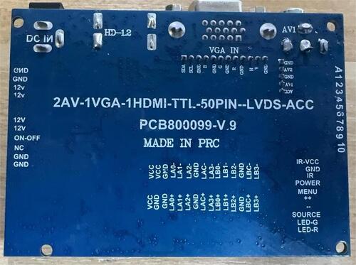
5 Product appearance diagram, without terminal style, as shown below

The full functional style with the terminal is as follows
6 Product size chart
7 Detailed description of the interface functions
7.1
J6 key board, remote control input interface
|
order number
|
definition
|
explain
|
|
1
|
5V
|
The remote control power supply is actually 3.3V
|
|
2
|
GND
|
the earth
|
|
3
|
IR
|
remote input
|
|
4
|
POWER
|
Switch machine function
|
|
5
|
MENU
|
Menu display function
|
|
6
|
+
|
add
|
|
7
|
_
|
subtract
|
|
8
|
SOURCE
|
Signal source conversion
|
|
9
|
LED-R
|
LED pilot lamp
|
|
10
|
LED-G
|
LED pilot lamp
|
DB15- -VGA signal input interface
|
order number
|
definition
|
explain
|
|
1
|
D-15
|
standard interface
|
The J1 high-voltage panel interface
|
1
|
+12V
|
Positive power input
|
|
2
|
+12V
|
Positive power input
|
|
3
|
EN
|
High-voltage board switch signal
|
|
4
|
empty
|
empty
|
|
5
|
GND
|
GND
|
|
6
|
GND
|
GND
|
CN1- - - - - -LVDS screen interface
|
order number
|
definition
|
explain
|
|
1
|
VCC
|
LCD screen power supply
|
|
2
|
VCC
|
LCD screen power supply
|
|
3
|
VCC
|
LCD screen power supply
|
|
4
|
GND
|
the earth
|
|
5
|
GND
|
the earth
|
|
6
|
GND
|
the earth
|
|
7
|
LAX0+
|
LVDS signal
|
|
8
|
LAX0-
|
LVDS signal
|
|
9
|
LAX1+
|
LVDS signal
|
|
10
|
LAX1-
|
LVDS signal
|
|
11
|
LAX2+
|
LVDS signal
|
|
12
|
LAX2-
|
LVDS signal
|
|
13
|
GND
|
|
|
14
|
GND
|
|
|
15
|
LACK+
|
LVDS signal
|
|
16
|
LACK-
|
LVDS signal
|
|
17
|
LAX3+
|
LVDS signal
|
|
18
|
LAX3-
|
LVDS signal
|
|
19
|
LBX0+
|
LVDS signal
|
|
20
|
LBX0-
|
LVDS signal
|
|
21
|
LBX1+
|
LVDS signal
|
|
22
|
LBX1-
|
LVDS signal
|
|
23
|
LBX2+
|
LVDS signal
|
|
24
|
LBX2-
|
LVDS signal
|
|
25
|
GND
|
|
|
26
|
GND
|
|
|
27
|
LBCK+
|
LVDS signal
|
|
28
|
LBCK-
|
LVDS signal
|
|
29
|
LBX3+
|
LVDS signal
|
|
30
|
LBX3-
|
LVDS signal
|
J3-DCIN power interface
|
1
|
+12V
|
Positive power input
|
|
2
|
+12V
|
Positive power input
|
|
3
|
GND
|
GND
|
|
4
|
GND
|
GND
|
HDMI joggle
|
1
|
HDMI standard interface
|
Standard wire available
|
J5, AV signal and reversing control power interface
|
1
|
ACC
|
Reversing voltage input, 12V input after forced to AV 2
|
|
2
|
AV1
|
AV1 input
|
|
3
|
GND
|
GND
|
|
4
|
AV2
|
AV2 input
|
|
5
|
GND
|
GND
|
J4-VGA IN
|
1
|
GND
|
GND
|
|
2
|
V
|
V
|
|
3
|
H
|
H
|
|
4
|
GND
|
GND
|
|
5
|
R
|
R
|
|
6
|
GND
|
the earth
|
|
7
|
G
|
G
|
|
8
|
GND
|
the earth
|
|
9
|
B
|
B
|
|
10
|
GND
|
the earth
|
|
11
|
SDA
|
Upgrade with
|
|
12
|
SCL
|
Upgrade with
|
CN3 definition
CN1- - - - - -LVDS screen interface
|
order number
|
definition
|
explain
|
|
1
|
A
|
Screen reference combination design
|
|
2
|
1
|
Screen reference combination design
|
|
3
|
2
|
Screen reference combination design
|
|
4
|
3
|
Screen reference combination design
|
|
5
|
4
|
Screen reference combination design
|
|
6
|
6
|
Screen reference combination design
|
|
7
|
7
|
Screen reference combination design
|
|
8
|
8
|
Screen reference combination design
|
|
9
|
9
|
Screen reference combination design
|
|
10
|
10
|
Screen reference combination design
|
|
11
|
11
|
Screen reference combination design
|
|
|
|
|
The screen parameter is set as shown in the following figure. which will continue to add different LCD screen parameters, up to 50 resolutions
CON 1, and the interface definition
8 Transportation, storage, and use requirements
1, Do not pressure and bend deformation
2, anti-static electricity and water
3, the relative humidity, less than 80%
4, use the temperature-1-degrees- - + 60 degrees
5,Use a humidity of 0- + 40 degrees
6,This drive board can use the remote control and key board pictures (optional)

|